の基本をマスターする準備はできているか? CNC旋盤加工?多くのメーカーが適切な製品を選ぶのに苦労している。 加工方法 円筒形部品の場合。これは無駄な時間、高いコスト、悪い結果につながる。.
で 5日目 CNC旋盤加工 財団, この重要なプロセスに関するすべてを学ぶことができる。そして CNC旋盤加工 とは何か、なぜそれが重要なのか、そしてどのようにそれを効果的に使うのか。この知識は、正確な部品をより早く、より安く作るのに役立ちます。.
なぜそれが重要なのか? CNC旋盤加工 のような産業に力を与えている。 自動車, 航空宇宙そして 医療機器. .厳しい精度でシャフト、ピン、継手を生産している。2026年には、世界の CNCマシン 市場は約791億4,000万米ドルで、2031年には1,047億6,000万米ドルに成長する(出典:Mordor Intelligence、2026年1月更新)。理解 CNC旋盤加工サービス は、競争の激しい分野であなたを優位に立たせる。.
私たちの CNC旋盤加工サービス これらの業界を専門家がサポートします。深く潜ってみよう。.
CNC旋盤加工の基礎
CNC旋盤加工 静止している切削工具がワークを除去している間にワークを回転させる。 材料 軸の周りに対称的な形状を作成する。この工程は、工具の位置、主軸の回転数、送り速度の精密な制御に依存しており、これらはすべてコンピュータ数値制御(CNC)システムによって管理されている。とは異なり ミーリング, 工具が回転するところでは、旋盤加工によるワークの回転が、シャフト、ブッシュ、継手を、しばしば0.0005インチ以内の同心度で効率的に生産することを可能にする。.
実際には、基本はワークの準備から始まる。未加工の素材-通常は棒材、ビレット、または鍛造材-がチャックに装填される。CNCコントローラーがGコード命令を実行し、X軸(半径方向)とZ軸(軸方向)に沿って工具を動かす。基本的なセットアップの場合、これはまっすぐな直径、テーパー、面を作成します。切削熱による熱膨張は、鋼の場合、摂氏0.001度あたり0.001インチ寸法を変化させる可能性があるため、クーラント戦略が早期に重要になります。.
エンジニアは、最初から切りくずの形成を考慮しなけれ ばならない。短く折れた切屑は簡単に排出され、工具を鈍らせ表面を傷つける再切削を防ぎます。長くて筋状の切屑はタレットに絡みつき、生産を停止させます。私は、アルミ切屑がスピンドルを包んだため、シフトの途中で生産を停止したことがあります。なぜ特定のパラメータを選択するのか?高い主軸回転数(最新の旋盤では6000RPMまで)は、切屑を細分化しますが、熱を増加させ、ステンレス鋼の加工硬化のリスクを高めます。決定ロジックは、材料の種類、工具寿命、サイクルタイムのバランスを取ります。大量生産の自動車用シャフトには速度を優先し、航空宇宙用のチタンには、部品1個あたり数千ドルのスクラップを避けるために工具の保全を重視します。.
物事がうまくいかないとき、基本的なことが原因を明らかにします。オーバーハングしたワークピースは切削力でたわみ、テーパーエラーにつながります。最終外径に近いバー径を指定することで、テーパー誤差を最小限に抑えることができます。 材料 を除去し、大ロットで20-30%のコスト削減を実現した。.
コアメカニクスとマシン構成
力学はトルク、剛性、減衰に依存している。スピンドルのトルクは 材料 除去率(MRR)-低トルクは厳しい切削で足を引っ張り、サイクルを延ばします。硬質鋳鉄製ベッドは振動を吸収し、DMG森のNTシリーズのような高級機のポリマーコンクリート製ベースは高調波をよりよく減衰させ、より微細な仕上げ(Ra 0.4ミクロン)を可能にする。.
構成は様々です:スイス型旋盤は主軸台をスライドさせて細長い部品を加工し、直径0.125インチ以下の医療用ピンに最適。水平旋盤は一般的な加工に適していますが、垂直旋盤は重力を利用して切りくずを落下させ、タービンハブのような重い円盤を扱います。ツインスピンドルのセットアップでは、部品の加工途中での移動が可能なため、左右対称の部品のサイクルタイムが半減します。.
トレードオフが多い。スイス製マシンは精度(公差0.0002インチ)に優れるが、直径は最大1.25インチに制限される。横型旋盤は汎用性があるが、深穴での切屑排出に苦労する。長さ対直径の比率が10:1を超える場合は、スイス製がたわみを抑えますが、そうでない場合は、標準的な水平旋盤で十分です。.
制限事項には、熱成長-が含まれる。機械 シフトによってウォームアップし、ゼロ点が0.0005インチずれます。予熱サイクルや温度補正されたスケールは、これを軽減します。私が監督したある航空宇宙産業では、摩耗したベアリングによるスピンドルの振れに対処していなかったため、50個のチタン製継手を廃棄した。.
軸システムとその意味
基本的な2軸(X/Z)システムは単純なプロファイルを扱いますが、軸外フィーチャーのために複数のセットアップを必要とし、誤差の蓄積を増加させます。C軸(主軸回転制御)を追加することで、以下のことが可能になります。 ミーリング ライブツールで、位置を変えることなく放射状の穴を開けることができます。.
Y軸は、キー溝のような偏心形状を可能にする垂直方向の動きを追加します。傾斜ヘッドまたはサブスピンドルを備えたフル5軸(X/Y/Z/B/C)は、以下のような複雑な形状に対応します。 メディカル インプラント.
意思決定への影響:2軸は大量の円筒部品のコストを低く抑えるが、5軸はセットアップを3回から1回に減らし、機械レートが高いにもかかわらずリードタイムを40%短縮する($150/時間に対して$80)。限界:Y軸は複雑さを増し、プログラミング時間と衝突リスクを高めるため、シミュレーションが必須。.
間違うとどうなるか?ラジアル穴が必要な部品に2軸を選択すると、2次加工が必要になり、20%のコストとミスアライメントのリスクが増える。1000個以下なら多軸が妥当、1000個以上なら専用治具が必要。.
CNC旋盤加工とは?
CNC旋盤加工 は減算法である。 加工工程 CNCとは、旋盤の上でワークピース(通常は金属やプラスチックなどの円柱状の棒)を高速で回転させながら、固定された切削工具で材料を削って形を整える加工方法である。コンピュータ数値制御(CNC)は、プログラムされた命令に基づいて、すべての動き、速度、切削を指示し、手作業ではかなわない一貫した結果を提供する。.
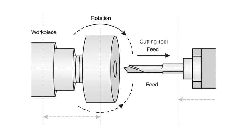
ワークピースはその中心軸を中心に回転し(スピンドルによって駆動)、工具はその軸に沿って直線的に(Z方向)、または中心に向かって放射状に(X方向)送ります。このセットアップは、直径、テーパー、ショルダー、溝、ねじ、面などの対称的な丸い形状を作成するのに適しています。工具は固定されたまま(送りは除く)部品が回転するため、力が予測通りに作用し、円筒形状の優れた同心度、真円度、仕上げ面精度が得られます。.
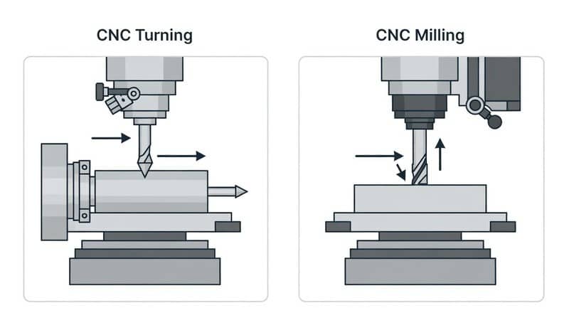
とは異なり CNCフライス加工, 切削工具は回転し、被削材は静止したまま(または多方向に動く)であるのに対し、旋削はその役割を逆転させる。旋盤加工では ミーリング, スピニング工具は、複雑な3次元輪郭、ポケット、スロット、平坦面を作成することができます。旋盤加工では、シャフト、ピン、ブッシュ、継手、ボルト、ローラーなど、回転対称の部品に重点を置いています。基本的なターニング・センターで非円形形状を加工しようとすると、ライブ・ツーリングやセカンダリ・ツーリングなどの追加機能が必要になります。 ミーリング セットアップを行う。.
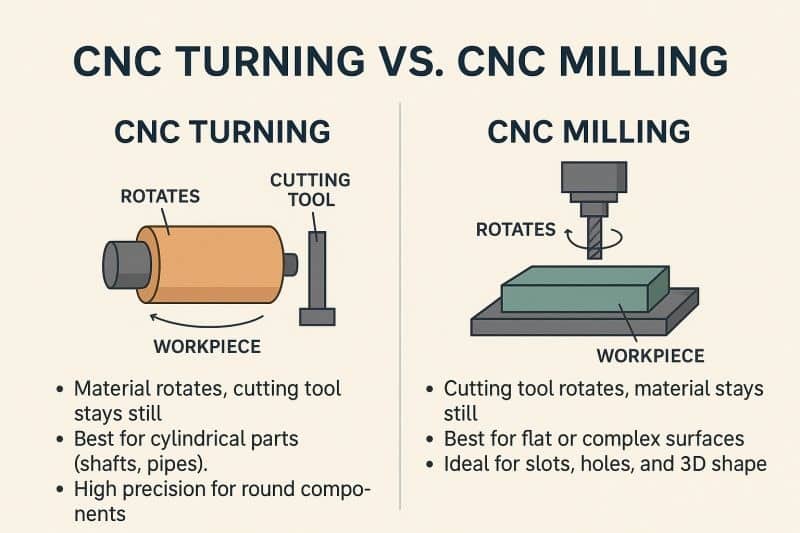
以下は、視覚的な比較である。 CNC旋盤加工, ワークピースは固定工具に対して回転する。 ミーリング, 部品が静止している間、工具は回転する。.
CNC旋盤加工の実際
そのプロセスは、切りくずが飛び散るずっと前から始まっている。実際の工場では、ただバーをチャックに放り込んでサイクルスタートを押すだけではありません。ここでは、2026年の環境における日常的な生産に基づいた、現場での展開について説明します。.
1.ワークのローディングとワークの保持
丸棒、六角棒、ビレットなど、長さに合わせて製材されるか、棒材として供給されることが多い。 材料. .主軸チャックに固定する。.
- 三爪セルフセンタリングチャック ほとんどの丸棒を素早く扱えます。ジョーは均一にグリップするが、ダイヤル・インジケータで振れをチェックすること。0.001″TIR(総表示振れ)を超えるものは、再チャックするか、最初に端面を真直にすることを意味する。.
- 4爪独立チャック または コレットチャック は、精密な形状や異形状で威力を発揮します。4本爪の場合、各爪をダイヤルイン(指示)してパーツの芯出しをする必要があり、5~15分かかるが、肉厚の薄いチューブや鋳物には歪みを避けるために不可欠。.
- 長いバー(直径6~8×以上)の場合は、次のようにする。 テールストック をライブ・センターで使用するか 安定した休息 ホイッピングを防止するため、中間に位置させる。これをスキップすると、公差を台無しにするテーパーエラーやビビリが発生する。.
大量生産セットアップでは、バーフィーダーがローディングを自動化し、完成品を切り離した後に新しいストックを前方に押し出すことで、マシンを何時間も無人で稼動させることができる。.
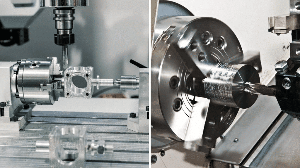
典型的な3爪チャックが部品を把持している様子で、噛み合わせ用の爪のセレーションと切削時のクーラントの飛散が確認できる。.
2.マシンのパワーアップ、原点復帰、プログラムのロード
電源オン 機械 (メインブレーカー+コントロールパネル)。ほとんどの最新旋盤(ファナック、シーメンス、ハース)には原点復帰が必要です:軸はゼロ位置を確立するために基準スイッチまで移動します。これには30~60秒かかり、停電またはE-stop後は必須です。.
USB、ネットワーク、DNC経由でGコードをロード。プログラムは以下の通り:
- ヘッダー(安全ライン:G20/G21ユニット、G54ワークオフセット、G28ホームリトラクト)
- 工具交換(工具1オフセット1の場合はT0101)
- スピンドル始動(M03/M04方向、Sxxxx RPMまたはG96一定表面速度)
- サイクルとモーション
- 終了(M30リセット)
実行する前に、プログラムをドライラン(グラフィックシミュレーションまたはスピンドルオフのエアカット)して、衝突がないことを確認してください。.
3.工具のセットアップとオフセット
タレットに工具を取り付ける。通常、超硬チップ(CNMG、WNMGなど)をホルダーに取り付ける。各工具をタッチオフする:
- 既知のサーフェスに面するか、ツールセッター/プローブを使用してZオフセットを設定する。.
- Xオフセットは、直径を回して測定(またはプロービング)して設定する。.
モダン 機械 自動ツールセッターを使用する-プローブがツールチップに触れ、オフセットが自動更新される。これにより時間を節約し、エラーを減らすことができる。.
4.スピンドル始動と初期位置決め
サイクルスタート。主軸はプログラムされた速度(例えば、鋼の場合は1500-4000RPM、アルミの場合は3000-6000+)にランプします。工具がスタート位置(G00)まで急降下します。.
コントローラはGコードを一行ずつ実行し、X/Z(および追加軸)をスピンドルの回転と調整する。.
5.コア切断の順序:荒削りから仕上げまで
ほとんどのプログラムはこの順序に従っている:
- フェイシング first - 端面を平らにし(G01またはG94サイクル)、きれいなZ-ゼロ基準を作成する。.
- ラフティング - 大量の在庫を素早く取り除く。以下のような定型サイクルを使用する。 G71 (ODラフィング)または G72 (ラフを向いて)。.
G71荒加工ブロックの例(一般的なファナックスタイル):
テキスト
G71 U1.5 R0.8;(U=ラジアル1.5mmパスあたりの切り込み量、R=後退量)
G71 P10 Q50 U0.4 W0.1 F0.25; (P/Q = プロファイル開始/終了ブロック、U/W = 仕上げ代 X/Z、F = 送り)
N10 G00 X105.0;(ラピッド~スタート径)
G01 Z2.0 F0.3; (feed to face start)
The machine takes multiple parallel passes along the profile, leaving allowance (U/W) for finishing.
Roughing prioritizes 材料 removal rate (MRR): deeper cuts (0.08–0.15″), moderate feeds (0.01–0.03 ipr), balanced speeds to avoid excessive heat.
- Semi-finishing (optional) — Light pass to stabilize dimensions before final cut.
- Finishing — Light depth (0.005–0.020″), higher speeds, lower feeds for Ra 0.8–1.6 μm (or better). Use G70 finishing cycle to follow the same profile as roughing but with finish parameters.
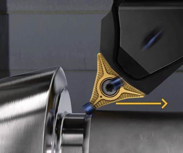
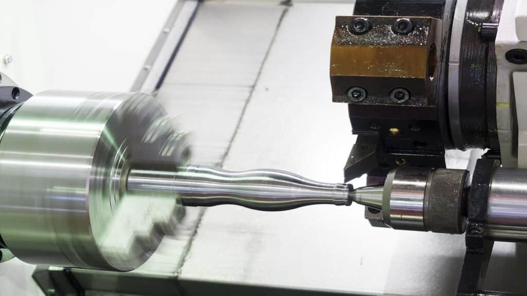
A New Turning Process Enables Cutting “In Reverse” | Modern Machine Shop
This shows a tool taking a cut on a rotating workpiece, with visible chip flow.
6. Coolant Application and Chip Management
Coolant floods the cut zone (flood or through-tool at 300–1000+ PSI). It cools the tool/workpiece, lubricates, and flushes chips.
Chip control is critical:
- Short, broken chips (C-shaped or segmented) evacuate easily via conveyor or fall harmlessly.
- Long stringy chips (common in aluminum, mild steel) wrap around the tool, part, or tailstock—causing crashes, poor finish, or downtime.
Techniques to break chips:
- Chipbreaker geometry on inserts curls or fractures chips.
- Feed modulation — Increase feed momentarily or use peck cycles.
- High-pressure coolant blasts chips apart.
- Oscillation cutting (some controls) varies feed sinusoidally.
- Parameter tuning — Higher feed often breaks better than speed alone.
Without good chip breaking, expect frequent stops to clear tangles—especially annoying on lights-out runs.
What is Chip Formation? | Market Prospects
Example of effective chip formation—short curls being ejected cleanly.
7. Advanced Operations with Live Tooling and Multi-Axis
On mill-turn centers:
- Live tools (driven turret stations) drill, mill, or tap while the spindle indexes via C-axis.
- Y軸 allows off-center features.
- Sub-spindle grabs the part for back-side work (chamfers, threads) without flipping manually.
Example: Drill cross-holes, mill flats, then transfer to sub-spindle for rear facing—all in one clamping.
This reduces setups, improves concentricity, and cuts lead time.
8. In-Process Monitoring, Parting Off, and Unload
Probe diameters mid-cycle (if equipped) and auto-adjust offsets for thermal drift or wear. After final pass, part off with a grooving tool or parting insert—use peck or oscillation to break the slug safely.
Unload the part (manual or robotic), deburr, inspect first piece (micrometers, CMM, surface profilometer), then run production.
In practice, the whole sequence—from load to unload—takes minutes for simple shafts to hours for complex mill-turn parts. Success depends on proven programs, stable setups, sharp tools, and vigilant monitoring. When chips flow right and tolerances hold run after run, that’s when turning feels routine—but it’s always built on careful preparation. For demanding jobs where in-house capacity or expertise falls short, experienced CNC旋盤加工サービス replicate this process reliably at scale.
Typical Precision and Tolerances You Can Expect
In real 2026 production environments, CNC旋盤加工 delivers repeatable dimensional accuracy that far exceeds manual lathe work, but the exact numbers depend on 機械 class, setup stability, 材料 behavior, tooling condition, and whether you’re running standard jobs or pushing for ultra-precision. Shops don’t chase the tightest numbers on every part—doing so inflates costs dramatically through slower cycles, more frequent tool changes, in-process probing, temperature-controlled environments, and extended inspection. Instead, tolerances align with functional needs: a general shaft might run ±0.01–0.02 mm, while a bearing journal demands tighter control.
Standard Tolerances in Everyday Production
Most shops default to ISO 2768 medium (m) grade unless the drawing specifies otherwise. This is the practical baseline for turned metal parts in 2026:
- Linear dimensions and diameters (general features): ±0.1 mm to ±0.2 mm for larger sizes (>30 mm), tightening to ±0.05–0.1 mm on smaller features. In inches, this translates to roughly ±0.002″ to ±0.008″ (0.05–0.2 mm).
- Well-designed, medium-volume parts (e.g., shafts, bushings, fittings in automotive or general engineering): ±0.01 mm to ±0.02 mm (±0.0004″ to ±0.0008″) on diameters. This assumes good 機械 rigidity (slant-bed lathe, direct-drive spindle), sharp carbide inserts, proper coolant, and no excessive overhang.
- Precision features (press fits, bearing seats, hydraulic valve spools, threaded interfaces): ±0.0025 mm to ±0.0125 mm (±0.0001″ to ±0.0005″). Shops achieve this routinely on stable setups with in-process gauging (probing), thermal compensation, and light finishing passes. Many high-end turning centers (e.g., DMG Mori, Okuma, Mazak with linear scales) hold ±0.005 mm (±0.0002″) consistently on diameters under controlled conditions.
These ranges come from shop-floor reality in 2026: standard horizontal lathes hit ±0.005″ (±0.127 mm) as a safe default (common at Protolabs, Xometry, and similar services), while precision-oriented shops push ±0.001″ (±0.025 mm) or better without secondary grinding. Ultra-tight work (±0.0002″ / ±0.005 mm) exists for メディカル implants or aerospace optics but often requires post-turn grinding or honing to guarantee it across a full batch.
Surface Finish Expectations (Ra Values)
Surface roughness directly ties to tolerances—finer finishes often require parameters that also tighten dimensional control.
- Standard “as-machined” finish (default for most runs): Ra 1.6–3.2 μm (63–125 μin). This leaves light tool marks visible under close inspection but feels smooth to the touch. It’s the baseline for brackets, housings, structural shafts—no extra cost, achieved with moderate feeds (0.01–0.02 ipr) and speeds.
- Fine functional finish (common for sliding surfaces, seals, bearing journals): Ra 0.8–1.6 μm (32–63 μin). Requires sharp inserts (positive rake, polished), low feeds (0.002–0.005 ipr), high speeds, and sometimes oscillation or variable feed to break chips without dwell marks.
- High-end achievable finish (without polishing): Ra 0.4 μm or better (16 μin or finer). Possible with diamond-tipped tools on non-ferrous, ultra-sharp carbide on steels, high-pressure coolant, and minimal depth of cut on the final pass. This level suits optical mounts, hydraulic pistons, or メディカル components where low friction and wear resistance matter.
In practice:
- Roughing leaves Ra 6.3–12.5 μm—visible lines, functional only for non-contact areas.
- Finishing drops to Ra 1.6 μm or below with careful control.
- Pushing below Ra 0.8 μm often adds 50–200% to cycle time and tool wear, so engineers reserve it for critical zones.
Factors That Influence Real-World Precision
No shop holds these numbers blindly—several variables push parts out of spec if unmanaged:
- Thermal expansion and machine warm-up — Steel expands ~0.012 mm per meter per °C. A 10°C rise shifts a 200 mm diameter by ~0.024 mm. Shops use spindle warm-up cycles, coolant chillers, or linear scales with thermal compensation to hold tight tolerances over long runs.
- Tool deflection and wear — Overhung boring bars or long turning tools flex under force. Deflection scales with length cubed—double overhang, eight times the error. Fresh inserts and rigid setups (BMT turrets, damped bars) keep it minimal.
- Vibration and chatter — Long slender parts (L/D >6:1) or interrupted cuts vibrate. Tailstock, steady rests, or reduced DOC/feed fix most cases.
- Material machinability — Aluminum holds tight easily; titanium work-hardens and generates heat, loosening tolerances unless peck-cut with high-pressure coolant.
- In-process vs. post-process gauging — Probing mid-cycle auto-corrects offsets for drift. Without it, batch variation creeps in from tool wear or ambient changes.
- Workholding — Poor chuck grip causes runout; thin walls distort under clamping force.
On long production runs (thousands of parts), the first and last pieces often differ by 0.005–0.01 mm without monitoring—common pain point in automotive or hydraulic jobs.
Why CNC Turning Delivers Reliable Results for Production
Computer control removes operator inconsistency—no hand-wheeling variations or fatigue. A proven program runs the same every cycle: identical toolpaths, speeds, feeds, and dwell times. This repeatability shines in medium-to-high volumes where consistency trumps one-off perfection.
Industries exploit this daily:
- 自動車 — Drive shafts, axles, pistons, CV joints. ±0.01 mm on journals ensures smooth rotation and low NVH (noise, vibration, harshness). Repeatability across 10,000+ parts keeps assembly lines humming.
- 航空宇宙 — Fasteners, bushings, fittings, landing gear pins. Tight concentricity (±0.005 mm) and surface finish (Ra 0.8 μm) prevent fatigue cracks under cyclic loads.
- メディカル — Implants, surgical instruments, connectors. Biocompatible titanium turned to ±0.005 mm with Ra 0.4 μm minimizes tissue irritation and ensures precise fit.
- General engineering — Rollers, spindles, valve bodies. Reliable diameters and finishes support bearings, seals, and dynamic balance.
When in-house equipment or expertise doesn’t align with volume, tolerances, or exotic materials, CNC旋盤加工サービス manage the full chain: CAD review for manufacturability, fixturing design, tooling selection, program optimization, in-process checks, and full traceability (CMM reports, 材料 certs). OEMs receive parts that drop straight into assembly without surprises, often with lead times shortened by dedicated production cells.
These capabilities—proven tolerances, consistent finishes, and rock-solid repeatability—make CNC旋盤加工 the backbone for cylindrical precision components in 2026. Push tolerances only where function demands it; over-specifying adds cost without benefit.
How Does CNC Turning Work?
CNC旋盤加工 works through a precise, repeatable sequence of steps that transform raw bar stock into finished cylindrical parts. The fundamental principle is subtractive 加工: a workpiece rotates rapidly on a spindle while one or more stationary cutting tools remove 材料 in controlled amounts. Computer numerical control (CNC) executes programmed instructions (G-code) to coordinate every movement, spindle speed, feed rate, and tool change, eliminating the variability of manual operation.
In modern shops in 2026, this process runs on horizontal or vertical CNC lathes (turning centers), often with added capabilities like live tooling, Y-axis, sub-spindles, and automatic probing. The result is high-precision parts with excellent concentricity, surface finish, and repeatability—ideal for medium-to-high volumes where consistency across thousands of pieces matters.
The process follows a clear, logical sequence from preparation to completion.
1. Load the Material — Secure a Bar or Rod in the Chuck
Begin by preparing and clamping the workpiece.
Raw material is typically round bar stock (aluminum, steel, titanium, brass, or plastics), cut to length or fed from a bar feeder for continuous production. Secure it in the spindle chuck:
- Three-jaw self-centering chuck — Fast for round stock; jaws grip evenly with hydraulic or pneumatic force.
- Four-jaw independent chuck — For irregular shapes or precise centering; requires manual indicating (dialing in) to minimize runout.
- Collet chuck — Preferred for precision bar work; provides superior concentricity but limited to specific diameters.
For long parts (length-to-diameter ratio >6:1), engage the テールストック with a live center to prevent deflection, or use a 安定した休息 for intermediate support. Misalignment here causes immediate taper errors or chatter.
In automated cells, robotic arms or bar feeders load stock, allowing lights-out operation.
2. Program the Machine — Use G-Code to Guide Movements
Before any cut, create or load the program.
- Start with a CAD model of the final part.
- Use CAM software (Mastercam, Fusion 360, GibbsCAM) to define stock, select tools, set operations (roughing, finishing, threading), and generate toolpaths.
- Post-process to output machine-specific G-code.
G-code includes commands like:
- G00 for rapid positioning
- G01 for linear feed
- G71/G72 for roughing cycles
- G76 for threading
- M03/M04 for spindle direction, S for speed
Modern practice includes full simulation (Vericut or built-in graphics) to detect collisions, gouges, or over-travel. Dry-run the program (no tool or air cut) before committing metal.
3. Rotate the Workpiece — Spindle Spins It at High Speed
Power up, home the axes (move to reference points for zero establishment), load the program, and start the cycle.
The spindle accelerates to programmed RPM—typically 500–6000+ RPM depending on diameter, 材料, and surface finish goal. Constant surface speed (G96) maintains optimal cutting velocity as diameter reduces.
Spindle power (15–50 HP common) and rigidity handle heavy roughing cuts without bogging down.
4. Move the Tool — Cutting Tool Removes Material Along X and Z Axes
The tool turret indexes to the active tool (carbide insert usually), and the CNC coordinates motion:
- Z軸 — Parallel to spindle centerline; controls length and axial features.
- X軸 — Radial; controls diameter (positive X moves away from center).
Basic 2-axis machines handle external diameters, faces, tapers, and simple profiles.
The tool feeds into the rotating workpiece, shearing 材料 into chips. Roughing uses deeper cuts (0.08–0.15″ DOC) and moderate feeds (0.01–0.03 ipr) for fast material removal. Finishing uses light cuts (0.005–0.020″) at higher speeds for smooth surfaces.
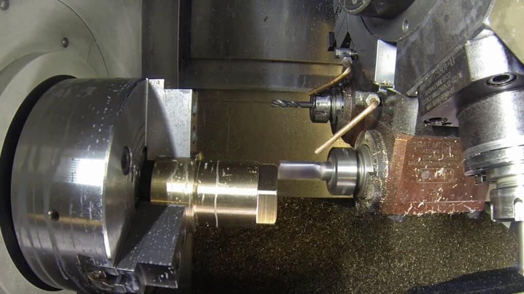
Coolant (flood or high-pressure through-tool) cools, lubricates, and flushes chips.

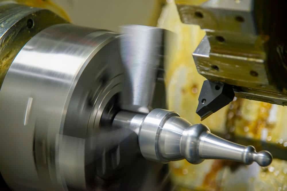
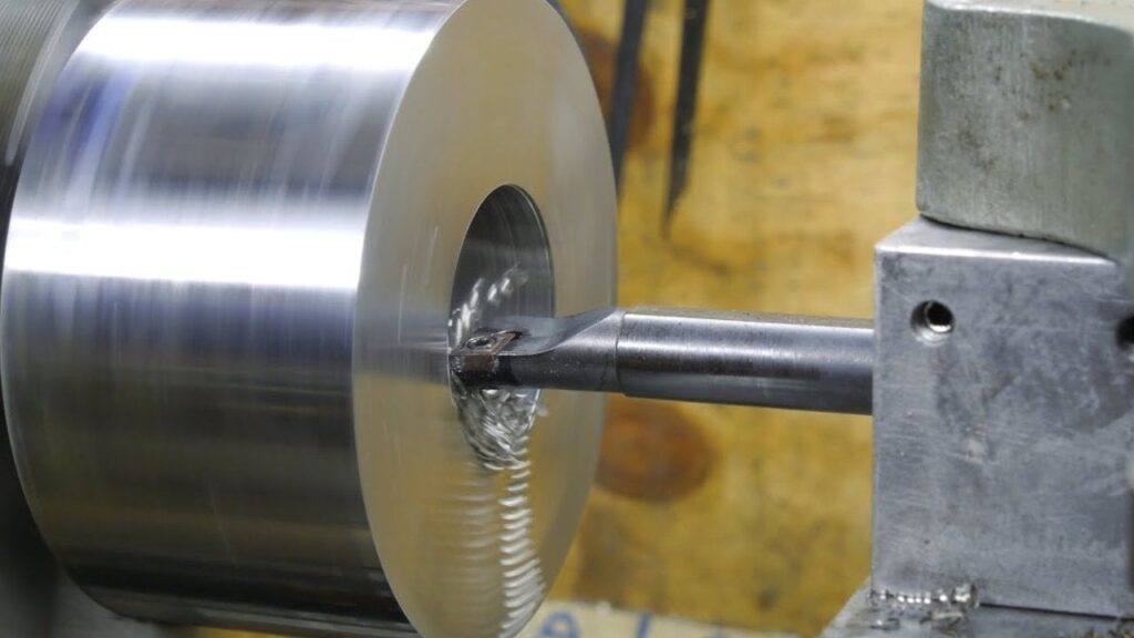
These illustrate the tool engaging the rotating workpiece, producing chips during a turning pass.
5. Finish Operations — Add Features Like Threads or Grooves
After rough and finish turning:
- Cut grooves, chamfers, or radii.
- Thread externally/internally using G76 cycle (multiple passes for depth control).
- Face ends for flat, square references.
- Bore internal diameters if needed.
On advanced centers, switch to live tools for secondary operations without repositioning.
6. Inspect and Unload — Check the Part and Remove It
Modern machines often probe mid-cycle or at key points—auto-adjust offsets for tool wear or thermal growth.
After final cut:
- Part off the finished piece (grooving/parting tool, often with peck to break the slug safely).
- Unload manually, via conveyor, or robot.
- Inspect critical dimensions (micrometers, CMM, profilometer) on first piece; sample or 100% inspect batches.
Deburr edges, clean, and prepare for secondary processes or shipping.
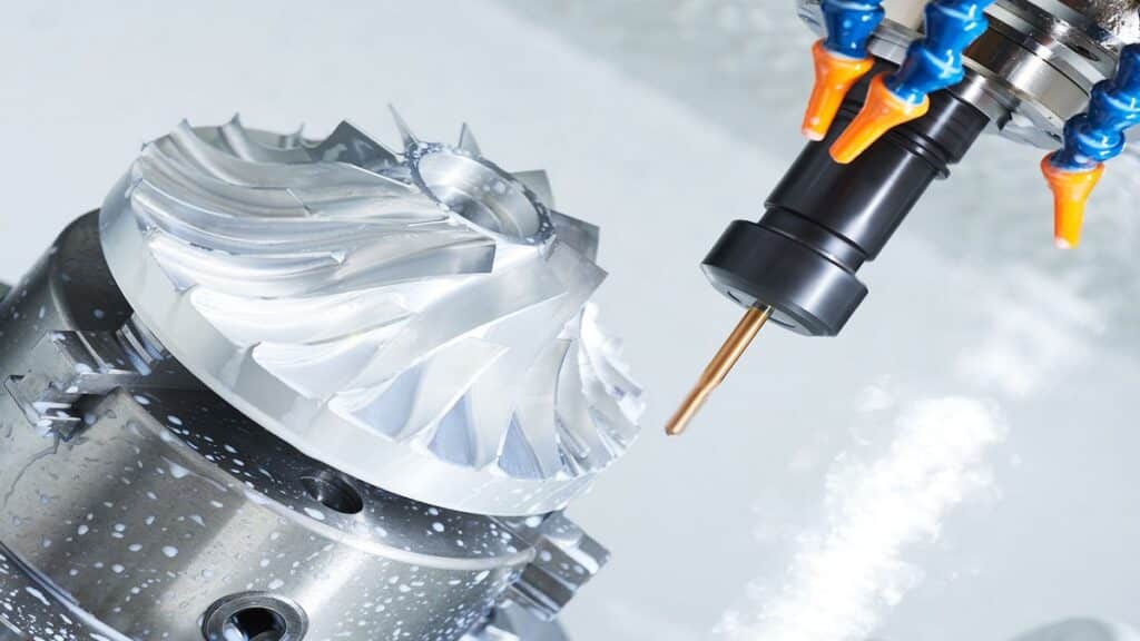
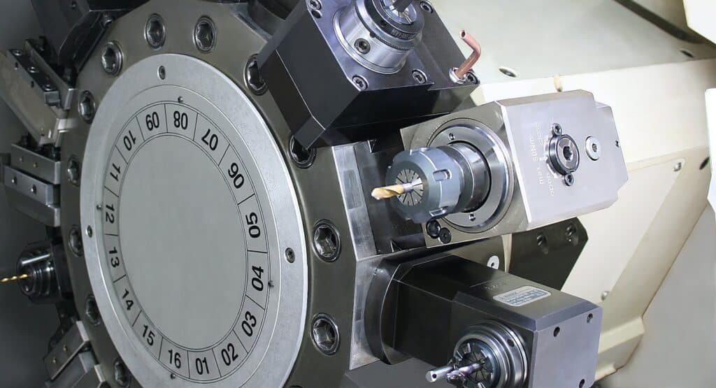
Modern Centers Add Live Tools for Milling on the Same Machine
Today’s turning centers integrate ミーリング via:
- Live tooling — Motorized turret stations that rotate tools (drills, end mills) independently.
- C軸 — Precise spindle indexing for angular positioning.
- Y軸 — Off-center movement for eccentric features.
- Sub-spindle — Transfers the part for back-side 加工 in one clamping.
This mill-turn capability completes complex parts (cross-drilled holes, milled flats, keyways) without secondary setups, boosting accuracy (no re-chucking errors) and slashing lead times.
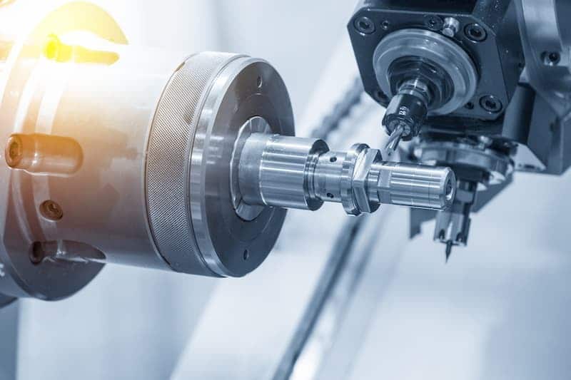
These show live tooling drilling and ミーリング on a rotating part.
This setup saves significant time—often 30–50% on parts needing mixed turning and ミーリング—and enhances precision by maintaining datum relationships. For jobs requiring these hybrid capabilities or high-volume consistency, CNC旋盤加工サービス deliver optimized processes from programming through inspection.
Main CNC Turning Operations
These are the core operations performed on CNC lathes and turning centers. Each targets specific features on cylindrical parts, using single-point tools for external/internal shaping or specialized tooling for threads, grooves, and holes. In 2026 production, these ops run on 2-axis lathes for basics or multi-axis mill-turn centers for integrated features, often in one setup to minimize handling and maintain datum accuracy.
Operations typically sequence as: face first (reference surface), rough OD/ID, finish passes, then secondary ops like grooving, threading, or live-tool drilling. Parameters (spindle speed, feed rate, depth of cut) adjust per 材料—aluminum allows aggressive cuts, titanium demands conservative to avoid heat and work hardening.
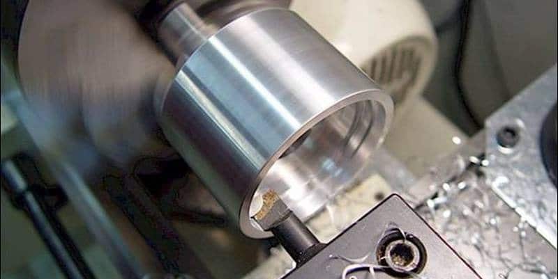
フェイシング
Facing creates a flat, perpendicular end surface on the workpiece. It’s almost always the first operation to establish a clean Z-zero datum and square the end for accurate length control.
The tool feeds radially inward from the outer diameter toward the center (or outward from a pre-drilled hole). Use a facing tool or OD turning insert with a lead angle for efficient chip flow.
- Why start here: Provides a reliable reference face; removes saw marks or uneven stock ends.
- Practical tips: Take multiple light passes if the end is uneven—first rough to clean up, then finish for flatness. Rigid setup prevents push-off; use positive-rake inserts for soft 材料 to reduce burrs.
- Common parameters: Higher spindle speed (2000–4000 RPM for steel), moderate feed (0.008–0.015 ipr), shallow DOC (0.02–0.05″) on finish.
- Issues if wrong: Convex/concave face from tool deflection or poor alignment—leads to length variation in batches.
These show a facing cut flattening the end, with the tool moving across the rotating face.
Straight Turning (OD Turning)
Straight turning reduces the outer diameter (OD) to create smooth cylinders, steps, tapers, or contours. It’s the heart of most turned parts.
- ラフティング — Removes bulk stock quickly. Deeper cuts (0.08–0.20″ radial DOC), higher feeds (0.015–0.040 ipr), moderate speeds to maximize MRR while preserving tool life.
- Finishing — Achieves final dimension and surface. Light DOC (0.005–0.020″), low feeds (0.002–0.008 ipr), higher speeds for Ra 0.8–1.6 μm.
Use canned cycles like G71 (rough) and G70 (finish) to automate profiling along the contour.
- Real application: Turning a shaft from 2″ bar to stepped diameters—rough in one cycle, finish for bearing fits.
- Challenges: Long overhangs cause deflection/taper; use tailstock or reduce DOC. Chip breaking essential—stringy chips from mild steel tangle without breakers or peck feeds.
Boring
Boring enlarges or refines existing internal diameters using a single-point boring bar fed parallel to the spindle axis.
Start with a pre-drilled or cored hole; the bar reaches in to achieve precise ID, straightness, and finish. Depth-to-diameter ratios over 4:1 risk vibration—use damped bars or carbide extensions.
- Key considerations: Minimize overhang (L/D <4 ideal); ensure clearance to prevent rubbing. Peck boring clears chips in deep holes.
- Parameters: Lower speeds than OD (due to heat buildup), feeds 0.004–0.012 ipr, DOC 0.01–0.05″.
- アプリケーション: Bearing housings, valve bodies—tolerances often ±0.0005″ for press fits.
- Pitfalls: Chatter from resonance; use anti-vibration bars or adjust speeds to shift harmonics.
Threading
Threading cuts helical grooves for external or internal threads using a pointed single-point tool.
CNC uses G76 (two-line or one-line format) canned cycle: defines pitch, depth, angle, and multiple passes (roughing infeed then spring passes for accuracy).
- External — Most common; tool feeds in at compound angle (29–30°) to reduce load.
- Internal — Requires boring first; similar cycle but careful clearance.
- Parameters: Low feeds per pass, spindle synced to Z motion. Chamfer entry/exit to avoid burrs.
- Examples: UNC/UNF bolts, metric threads, Acme for leadscrews.
- 精密: Pitch accuracy critical; use thread gauges post-cut.
Threading in action and G76 cycle diagrams showing multi-pass infeed.
Grooving and Parting
Grooving cuts narrow recesses (O-ring, snap-ring, relief); parting severs the finished part from stock.
Use dedicated grooving/parting inserts—rigid holders critical to resist deflection.
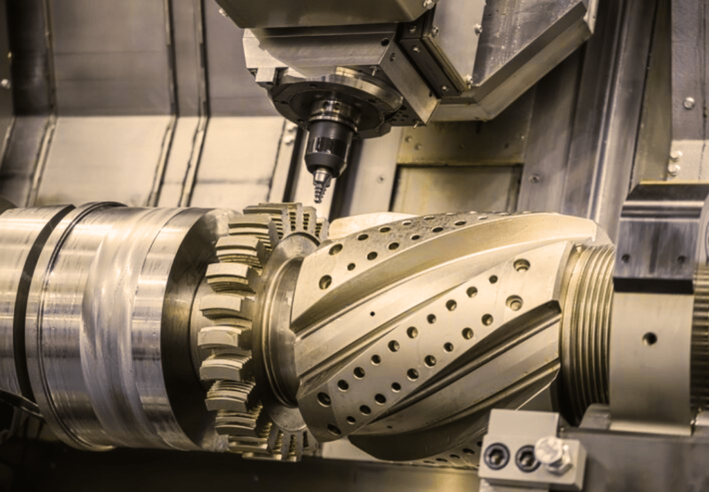
ドリリングとタッピング
Drilling creates axial holes; tapping forms internal threads in those holes.
- 掘削: Center drill first for spot, then peck cycle (G83) to clear chips in deep holes—prevents packing and breakage.
- タッピング: Rigid tapping (spindle reverses synced) or tension/compression holders. Peck tapping for deep threads.
- Live tooling advantage: Drill/tap radially or on face without stopping rotation—uses C-axis indexing.
On basic lathes, drill from tailstock; mill-turn centers use live tools for cross-holes.
Live tooling setups drilling/tapping on lathe turret, showing motorized holders.
These operations cover 90%+ of turned features. Sequence them logically (face → rough → finish → secondary), optimize parameters per material, and use probing for in-cycle verification to hit tolerances consistently. For complex parts blending these ops, CNC旋盤加工サービス with mill-turn expertise deliver single-setup efficiency.
CNC旋盤加工の利点
CNC旋盤加工 stands out in precision manufacturing because it exploits the inherent strengths of rotational symmetry for cylindrical and axisymmetric parts. The workpiece spins while the tool feeds linearly, allowing continuous cutting action that delivers high 材料 removal rates, superior concentricity, and finishes that often eliminate secondary operations. In 2026 shop environments—where tolerances tighten, volumes fluctuate, and lead times compress—these advantages compound into measurable gains in quality, throughput, and cost control.
Here are the primary reasons engineers and procurement teams choose CNC旋盤加工 over alternatives like ミーリング, manual lathes, or other processes.
High Precision and Repeatability
CNC旋盤加工 routinely holds tolerances of ±0.0002″ to ±0.001″ (±0.005 mm to ±0.025 mm) on diameters in production, with concentricity and roundness often better than 0.0005″ TIR due to the single-axis rotation minimizing geometric errors. Once the program is proven (toolpaths, offsets, feeds/speeds locked), every part repeats identically—batch after batch, shift after shift—without operator intervention.
This repeatability stems from:
- Closed-loop servo control and linear scales on modern machines compensating for thermal growth and backlash.
- Consistent tool engagement—no interrupted cuts or varying forces like in ミーリング.
- Probing and auto-offset adjustments mid-run to counter tool wear or ambient changes.
In practice, this means first-piece approval covers the entire run: a hydraulic spool or aerospace bushing from part 1 matches part 10,000 within microns. Manual lathes can’t match this—human variability introduces 0.005–0.010″ scatter even with skilled operators. Compared to ミーリング, turning achieves tighter roundness and runout on cylindrical features without multiple setups that accumulate errors.
Fast Production for Cylindrical Parts
For round geometries, turning removes 材料 faster than any other method. Continuous tool contact and high spindle speeds (often 3000–6000+ RPM) yield exceptional MRR—frequently 2–5× higher than equivalent milling operations on similar stock.
- Cycle times drop dramatically for shafts, pins, fittings: a 12″ shaft with stepped diameters might run in 3–8 minutes per piece on a modern lathe vs. 15–30 minutes ミーリング from billet.
- Bar feeding or sub-spindle transfer enables unattended or lights-out runs, pushing OEE above 85% in high-volume cells.
- In 2026, AI-optimized toolpaths and adaptive control further shave 10–30% off cycles by real-time adjustment.
This speed shines in medium-to-high volumes (100–10,000+ pieces), where setup amortizes quickly and continuous cutting maximizes spindle utilization.
Less Material Waste
Turning starts from near-net bar stock, removing only what’s necessary radially—typically 10–30% less waste than ミーリング a part from a cube or plate. Optimized nesting in bar stock (especially with bar feeders) minimizes drop-offs, and precise programming avoids over-cutting allowances.
- Scrap rates often fall below 2–5% in well-run jobs, vs. 10–20%+ in manual or less-optimized processes.
- Near-net forgings or extruded blanks further reduce starting 材料, cutting costs on expensive alloys like titanium or Inconel.
- Chip recycling is straightforward—clean, uniform chips from turning sell at higher value than mixed ミーリング swarf.
Lower waste directly lowers per-part material cost, especially critical in aerospace/メディカル where titanium or superalloys dominate.
Excellent Surface Finishes
The continuous, tangential tool contact produces inherently smooth surfaces—Ra 8–63 μin (0.2–1.6 μm) standard, down to Ra 4–16 μin (0.1–0.4 μm) with sharp inserts, low feeds (0.001–0.004 ipr), high speeds, and high-pressure coolant.
- No tool marks from retracts or step-overs like ミーリング.
- Finishing passes often suffice without polishing or grinding, saving 20–50% on secondary ops.
- In sealing surfaces, bearing journals, or メディカル implants, this reduces friction, wear, and galling—extending component life.
Cost-Effective for Medium to High Volumes
Initial programming and setup cost more than manual, but per-part economics flip quickly:
- Setup amortizes over 100–500+ pieces.
- Reduced labor (one operator oversees multiple 機械) and minimal rework from errors.
- Shorter cycles and higher throughput lower machine-hour burden.
- In 2026, automation trends (palletized cells, robotic tending) push effective rates even lower for volumes above 1000.
For prototypes or very low runs (<50), manual or 3Dプリンティング may edge out, but turning wins decisively from 100+ where consistency and speed dominate total landed cost.
Handles Various Materials
CNC turning machines process a broad range effectively:
- Soft/easy: aluminum, brass, plastics (high speeds, aggressive feeds).
- Tough: steels, stainless (balanced parameters to manage heat/chips).
- Exotic: titanium, Inconel, Hastelloy (ceramic/CBN inserts, high-pressure coolant, slow speeds to avoid notching).
Rigid setups, variable spindle power, and adaptive controls make it versatile—often the same 機械 runs aluminum prototypes one shift and titanium production the next.
Real-World Impact in Automotive and Aerospace
In automotive, turning produces drive shafts, axles, pistons, and CV joints with journal tolerances ±0.0005″ and finishes Ra 16 μin—ensuring smooth rotation, low vibration, and long bearing life. High repeatability across millions of parts keeps assembly lines running without fit issues.
In aerospace, bushings, fasteners, fittings, and landing gear components demand concentricity <0.0002″ and fatigue-resistant surfaces. Turning delivers this in heat-treated alloys with minimal distortion, reducing NDT failures and scrap.
Compared to manual lathes, CNC slashes errors (no hand-cranking variability), cuts labor (no constant attendance), and boosts output 5–10×—critical under skilled-labor shortages in 2026.
These advantages make CNC旋盤加工 the default for rotational parts: unmatched efficiency where geometry aligns, delivering reliable, high-quality components at scale. For demanding runs or when in-house capacity lacks the right 機械, CNC旋盤加工サービス replicate these benefits with proven setups and expertise.

CNC旋盤
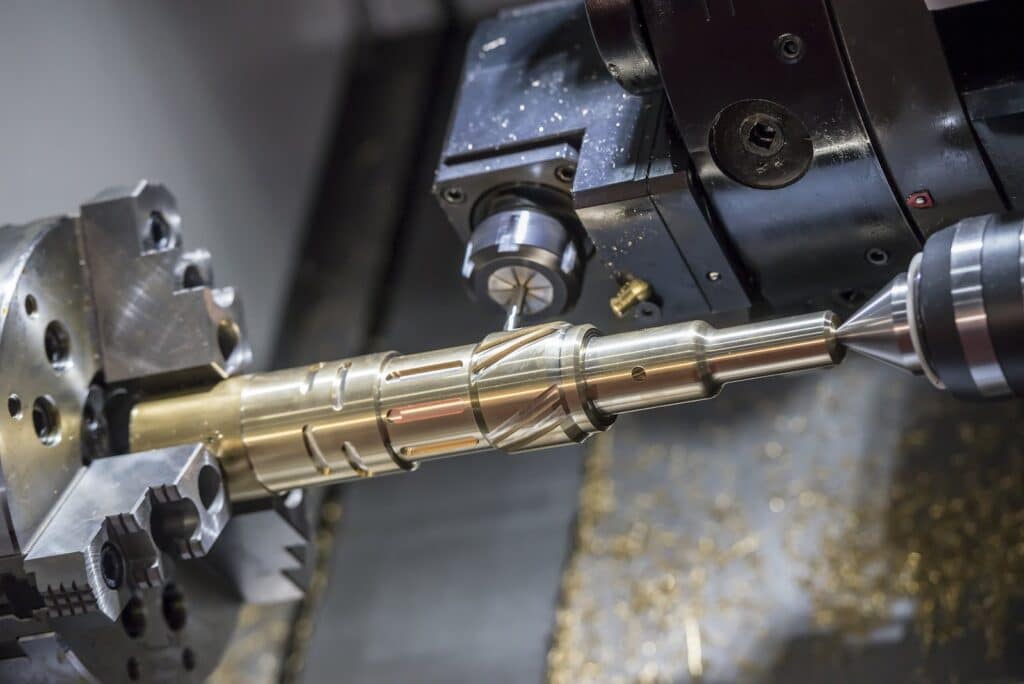
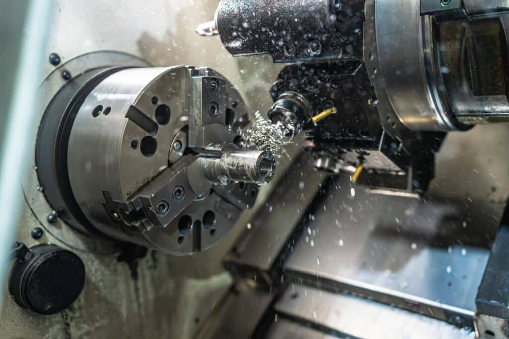
These show CNC旋盤加工 in action—precise cuts on rotating stock producing smooth, accurate cylindrical features.
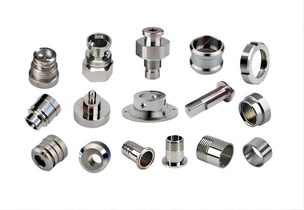
Examples of finished CNC turned parts—shafts, fittings, bushings—typical in automotive, aerospace, and precision applications.
CNC Turning vs. CNC Milling: Quick Comparison
| アスペクト | CNC旋盤加工 | CNCフライス加工 |
| Workpiece Movement | Rotates | Stationary |
| Tool Movement | Linear (stationary tool) | Rotates and moves |
| 最適 | Cylindrical, symmetrical parts | Complex shapes, flats, pockets |
| スピード | Faster for round parts | Versatile but slower for cylinders |
| 公差 | Often tighter (±0.0005″) | ±0.001″ typical |
Use turning for shafts. Use milling for brackets. Many shops combine both in mill-turn centers.
Industries That Rely on CNC Turning
CNC旋盤加工サービス serve key sectors.
- 自動車 — Shafts, pistons, fittings
- 航空宇宙 — Turbine components, fasteners
- メディカル — Implants, surgical tools
- エレクトロニクス — Connectors, housings
These industries demand precision. CNC旋盤加工 delivers it consistently.
Link to your industry pages for more details.
How to Choose the Right CNC Turning Service
Selecting a CNC旋盤加工サービス isn’t about the lowest quote—it’s about finding a partner whose capabilities, processes, and track record align with your part requirements, volume, tolerances, 材料, and industry demands. In 2026, with tighter supply chains, rising material costs, and increasing emphasis on traceability in regulated sectors, poor choices lead to delayed launches, rejected batches, or costly redesigns. A reliable service prevents these by delivering consistent parts that drop into assembly without surprises.
Follow this practical, shop-floor-validated guide. Ask pointed questions, request evidence, and compare multiple providers (aim for 3–5 quotes) to spot differences in real capability.
1. Check Machine Capabilities (Axes, Live Tooling, Capacity)
Start here because mismatched equipment kills feasibility or inflates costs through extra setups.
- Axis count and configuration — Basic 2-axis lathes handle simple shafts and bushings. For parts needing radial holes, milled flats, cross-drilling, or off-center features, demand live tooling (driven turret stations), Y-axis, C-axis indexing, and ideally a sub-spindle for single-setup back-side work. Ask: “What is your max turning diameter, length between centers, bar capacity, and live-tool RPM/power?” Look for slant-bed 機械 with rigid BMT turrets for heavy cuts without chatter.
- Mill-turn integration — If your design mixes turning and ミーリング, confirm they run true mill-turn centers (e.g., DMG Mori NTX, Okuma Multus, Mazak Integrex). This avoids secondary ops that add 20–40% cost and risk misalignment.
- Capacity and redundancy — Verify spindle count and shift coverage. For production (500+ pieces), ask about duplicate 機械 or backup cells to handle breakdowns or spikes. Inquire about bar feeders for unattended runs on bar stock.
Pro tip: Request machine list with models, years, and photos. A shop with 2018+ multi-axis lathes is more likely to hold tight tolerances than one running 2005-era 2-axis 機械.
2. Review Material Expertise
Not every shop 機械 every alloy well—exotics like titanium, Inconel, or Hastelloy require specific tooling, coolant strategies, and parameter knowledge to avoid work hardening, notching, or cracking.
- Ask for their experience with your exact materials (e.g., 6061 aluminum, 17-4 PH stainless, Ti-6Al-4V, Delrin). Request recent examples or material certs they’ve processed.
- Probe deeper: “Do you use high-pressure through-tool coolant? Ceramic/CBN inserts for hard materials? Variable-helix tools for chip breaking in gummy alloys?”
- For regulated industries (自動車, 航空宇宙, メディカル), confirm full traceability—mill certs, heat-treat records, RoHS/REACH compliance.
Shops strong in your 材料 reduce scrap and cycle time—saving you 15–30% overall.
3. Ask About Tolerances, Certifications, and Quality Systems
Tolerances aren’t just numbers on a print—they reflect the shop’s process control.
- Achievable tolerances — Standard: ±0.0005″ to ±0.001″ on diameters; precision shops hit ±0.0002″. Ask for capability data (CpK >1.33 on critical features) and recent PPAP or FAIR reports.
- 認証 —
- ISO 9001:2015 baseline for general quality.
- AS9100D for 航空宇宙 (risk management, traceability, counterfeit prevention).
- ISO 13485 for メディカル (validation, sterilization compatibility).
- ITAR registration for defense/aerospace (export-controlled parts).
- NADCAP for special processes if needed (e.g., heat treat, NDT).
- Quality control — Inquire about in-process probing, CMM usage, SPC charting, and final inspection. Ask: “How do you handle thermal compensation? Tool wear monitoring? Calibration frequency?”
A shop with these systems catches issues early—preventing batch rejections that cost weeks.
4. Look at Lead Times, Production Capacity, and Scalability
Lead time reliability separates partners from headaches.
- Request typical and worst-case timelines for prototypes (1–50 pcs) and production (500–10,000+).
- Ask about current utilization and backlog—overloaded shops miss dates.
- Evaluate scalability: Can they ramp from prototype to full production without new setups or subcontractors? Look for dedicated cells or redundant machines.
- Communication: How do they update on delays? Expect weekly status if critical.
In 2026, with ongoing supply volatility, prioritize shops that offer realistic ETAs backed by historical on-time delivery metrics (>95%).
5. Request Case Studies, Samples, and References
Proof beats promises.
- Ask for recent case studies or photos of similar parts (same 材料, tolerances, volume) in your industry (自動車 shafts, 航空宇宙 fittings, メディカルimplants).
- Request sample parts or first-article inspection reports to verify actual performance.
- Ask for 2–3 references from similar customers—call them to confirm on-time delivery, quality, and responsiveness.
- Evaluate DFM (design for manufacturability) feedback: A good service reviews your CAD, suggests tweaks (e.g., relaxed non-critical tolerances, added chamfers, standard radii) to cut costs 10–30% and improve manufacturability.
Expert advice: Send your print early for a free DFM review—shops that provide detailed feedback (redlines, cost drivers) show engineering depth and partnership mindset.
Additional Practical Checks
- Quoting transparency — Clear breakdown: setup, 材料, cycle time, tooling, finishes. Watch for hidden fees (programming, fixturing, expediting).
- Communication & responsiveness — Quick quote turnaround (24–48 hours), English-speaking engineers, same-time-zone preference for complex jobs.
- Location & logistics — Domestic for speed/IP protection; offshore for volume cost savings—but factor tariffs, shipping, and duties.
- Post-processing & finishing — In-house anodizing, plating, passivation, heat treat? Reduces vendors and lead time.
- Contract terms — NDA protection, payment schedule, liability, revision handling.
A strong CNC旋盤加工サービス acts as an extension of your team: they challenge assumptions, optimize designs, and deliver parts that meet or exceed specs on time. Start with these steps, compare side-by-side, and prioritize long-term fit over short-term savings. For your next project in 自動車, 航空宇宙, メディカル, or general engineering, the right partner turns potential headaches into seamless production. Submit an RFQ with your drawings and requirements—experienced services respond with insightful quotes and DFM suggestions to get you started right.
Common Mistakes to Avoid in CNC Turning
In real shop environments, most turning problems trace back to a handful of recurring errors that compound into scrap, downtime, broken tools, and missed deliveries. These aren’t theoretical—they show up daily on production floors in 2026, especially under pressure to hit aggressive cycle times or tight tolerances. The good news: nearly all are preventable with awareness, disciplined setup, and basic verification steps. Here are the most frequent and costly mistakes, why they happen, what they look like in practice, and how experienced machinists and programmers stop them before parts hit the floor.
1. Wrong Feeds and Speeds
This is the single biggest source of tool breakage, poor surface finish, dimensional variation, and excessive wear.
- What goes wrong: Too high speed + too low feed = built-up edge (BUE) on soft 材料 like aluminum or mild steel, leading to rough finish and tearing. Too low speed + high feed = excessive torque load, stalling the spindle or snapping inserts. Too aggressive overall = rapid flank/crater wear, notching on titanium/Inconel, or thermal cracking on carbide.
- Real-world signs: Chatter marks, blue chips (overheating), stringy birds-nest chips instead of controlled breakage, premature insert failure after 20–50 parts instead of hundreds.
- Why it happens: Copying old parameters without adjusting for new 材料 lot, tool coating, 機械 rigidity, or coolant condition. Or chasing shorter cycle time without validating tool life.
- How to avoid:
- Start with manufacturer-recommended starting points (Sandvik, Kennametal, Iscar charts) adjusted for your specific alloy, hardness, and insert grade.
- Use constant surface speed (G96) for consistent chip load across diameter changes.
- Monitor first few parts: check chip color/shape, listen for harmonics, measure insert wear after 10–20 cycles.
- Document proven parameters per 材料/tool combo in a shop library—don’t rely on memory.
2. Poor Workholding
Inadequate or incorrect fixturing causes the majority of out-of-round, taper, and runout failures.
- What goes wrong: Insufficient grip pressure lets the part slip under cutting forces → tool crashes or gouges. Excessive pressure distorts thin-wall tubes or delicate features (oval bores, crushed diameters). Misaligned chuck jaws or worn collets introduce runout >0.002″.
- Real-world signs: Concentricity fails on multi-diameter parts, bearing journals show lobing, long parts whip and produce severe taper.
- Why it happens: Assuming three-jaw self-centering is always accurate (it isn’t on worn jaws), skipping dial-in on four-jaw, not using tailstock/steady on L/D >6:1, or ignoring part material (aluminum yields more than steel under clamp force).
- How to avoid:
- Indicate every setup—aim for <0.0005″ TIR on critical jobs.
- Use soft jaws bored to part OD for delicate or repeat work.
- Apply correct clamping pressure (use gauge or torque wrench); hydraulics auto-regulate better than manual.
- For slender parts: tailstock live center + pressure check, or steady rest positioned to minimize deflection.
- Verify after warm-up—thermal growth can change grip.
3. Ignoring Chip Control
Bad chip formation turns a smooth run into a crash or quality nightmare.
- What goes wrong: Long stringy chips wrap around the tool, part, tailstock, or probe → collision, marred surfaces, or broken live-tool motors. Packed chips in bores/grooves recut and ruin finish or break tools.
- Real-world signs: Birds-nest tangles halting cycle, re-cut marks on diameter, premature tool failure from chip abrasion.
- Why it happens: Wrong insert chipbreaker geometry for the material/feed, no peck cycles in deep holes/grooves, low-pressure coolant, or pushing feeds too high without testing.
- How to avoid:
- Select inserts with appropriate chip control (e.g., positive rake + breaker for aluminum, negative with strong edge for steel).
- Use peck drilling/boring (G83/G87) in deep features—retract fully to clear.
- High-pressure through-tool coolant (500–2000 PSI) blasts chips away.
- Add oscillation or variable feed in CAM if needed.
- Run short test cycles to confirm chip shape before full production.
4. Skipping or Delaying Maintenance
Neglecting machine care shortens spindle, turret, and way life dramatically.
- What goes wrong: Worn spindle bearings increase runout → poor concentricity and chatter. Dirty ways/guides cause stick-slip → inconsistent dimensions. Unlubricated ball screws wear prematurely.
- Real-world signs: Growing taper over a shift, vibration increase, spindle growl or heat, offset drift requiring constant tweaking.
- Why it happens: Production pressure— “we’ll do it next downtime”—until a breakdown stops the line.
- How to avoid:
- Follow OEM daily/weekly/monthly checklists: grease points, way lube, air filters, coolant concentration.
- Warm-up spindle 20–30 min before tight-tolerance runs.
- Track spindle hours and schedule bearing checks/replacement at OEM intervals (typically 10,000–20,000 hours).
- Use vibration monitoring sensors on critical 機械 to catch bearing wear early.
5. Overlooking Material Properties
Treating all steels the same or ignoring heat-treat condition leads to unexpected behavior.
- What goes wrong: Work hardening in stainless/titanium from dull tools or high feeds → rapid wear or cracking. Heat buildup in low-conductivity alloys warps thin features. Sulfur-free steels string chips badly.
- Real-world signs: Sudden tool failure mid-batch (new lot harder than previous), distorted parts after unclamping, poor finish on supposedly easy material.
- Why it happens: Assuming mill cert matches previous stock, not verifying hardness/Rb, skipping test cuts on new material.
- How to avoid:
- Request and review material certs—check actual hardness vs. nominal.
- Run a test piece or short run on new lots to dial in parameters.
- Adjust for condition: annealed vs. heat-treated, cast vs. wrought.
- Use appropriate insert grades/coatings (e.g., PVD for stainless, CVD for steel).
Additional High-Impact Mistakes
- Skipping program simulation/verification — Leads to crashes (turret into chuck, tool into tailstock). Always simulate in CAM and dry-run on machine.
- No first-piece inspection protocol — Entire batch out of spec from uncaught thermal drift or offset error.
- Ignoring coolant maintenance — Diluted or contaminated coolant reduces tool life 30–50% and worsens finish.
- Poor tool offset management — Wrong offsets from manual touch-off or probe errors cause undersize/oversize parts.
Pro Tip from the Floor: Always simulate programs in software (Mastercam/Vericut) and on-機械 graphics before cutting metal. Then run the first part at 50% feed override while watching closely—catch 90% of issues before committing to full speed. Document everything: parameters, setup photos, first-piece measurements. The five minutes spent preventing a crash or scrap batch pays back tenfold in uptime and profitability.
Avoid these pitfalls consistently, and CNC旋盤加工 becomes one of the most reliable, efficient processes in the shop. For complex or high-stakes jobs where in-house experience is thin, partnering with a proven CNC旋盤加工サービス that already has these disciplines built in can save significant time and risk.
Cost Factors in CNC Turning
Costs vary.
- Setup time
- Material type
- Part complexity
- Volume (higher volume lowers per-part cost)
Tight tolerances raise costs exponentially. Optimize designs early.
For prototypes, expect higher per-part prices. Production runs save money.
結論
DAY 5 – CNC Turning (Foundation) covers the essentials you need. You now understand the process, operations, benefits, and pitfalls.
Apply this knowledge to create better parts. Whether prototyping or producing in volume, CNC旋盤加工 delivers results.Ready to start? Explore our CNC旋盤加工サービス for expert support in your industry. Contact us for a quote or advice on your next project.
よくある質問
CNC旋盤加工とCNCフライス加工の違いは何ですか?
CNC旋盤加工は、丸い形状の場合、固定された工具に対して部品を回転させます。CNCフライス加工は、工具を回転させて平坦な形状や複雑な形状を切削します。旋盤加工は円柱を得意とし、フライス加工は様々な形状を得意とします。.
CNC旋盤加工に最適な素材は?
アルミニウム、真鍮、スチール、ステンレススチール、チタン、デルリンなどのプラスチック。柔らかい素材は、より速く、より良い仕上げで加工できます。.
CNC旋盤加工の精度は?
It achieves tolerances from ±0.0005″ to ±0.003″. Factors include machine quality, tooling, and setup.
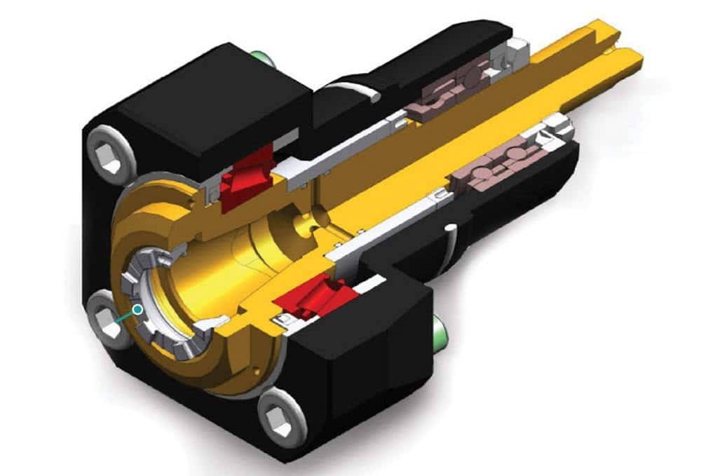
CNCターニングセンターとは?
複数の軸を持つ高度な旋盤で、多くの場合、フライス加工/ドリル加工のためのライブツーリングを1つのセットアップで行う。基本的な旋盤よりも複雑な部品を扱う。.
どのような場合にCNC旋盤加工を使うべきか?
For parts with rotational symmetry like shafts, pins, or bushings. It’s ideal when you need high volume or tight round features.