Introduction: Understanding CNC Machining in Depth
CNC (Computer Numerical Control) machining is a vital and versatile manufacturing process that allows for the precise production of complex parts from various materials. For engineers, OEM buyers, and procurement managers, it is essential to have a comprehensive understanding of how CNC machining works, why certain decisions are made, and the trade-offs involved in every step of the process.
This article will provide a deep, expert-level explanation of the complete CNC machining process from beginning to end, touching on the key decisions made during production, real-world examples from the shop floor, and the practical challenges that engineers and procurement managers face when dealing with CNC machining projects.
What is CNC Machining?
At its core, CNC machining refers to the use of computer-controlled machines to perform a variety of machining tasks, such as milling, turning, drilling, and grinding. The machines operate based on pre-programmed instructions (G-code), which guide them through a series of movements to cut or shape raw materials into finished parts.
Key CNC Machining Methods
CNC machining can be divided into several methods, each suited to different types of operations and part geometries:
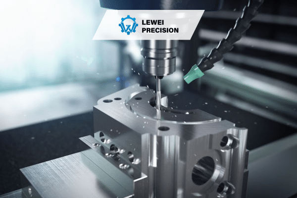
- CNC Milling: A process where a rotating cutter is used to remove material from a stationary workpiece.
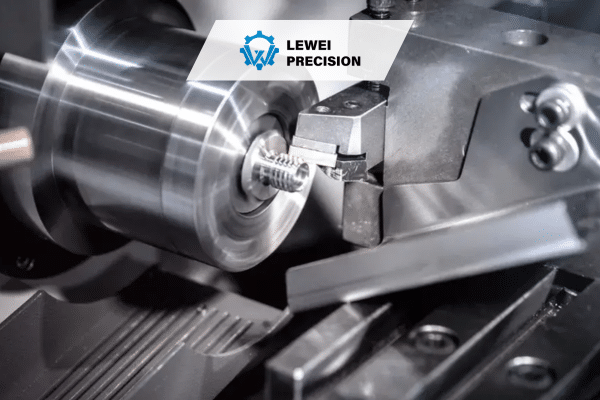
- CNC Turning: The workpiece rotates while the cutting tool remains stationary to create cylindrical parts.
- CNC Drilling: A rotating drill bit creates round holes in the material.
- CNC Grinding: Abrasive wheels are used to achieve high-precision finishes on parts.
Each method serves a distinct purpose, but they all share the underlying principle of using a computer to automate precision cutting and shaping.
Step 1: Designing the Part with CAD
The CNC machining process begins with the creation of a 3D model of the part to be produced. This is done using Computer-Aided Design (CAD) software, which allows engineers and designers to specify exact geometries, tolerances, and material properties.
Real-World Example:
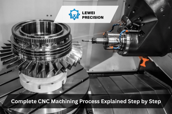
In the aerospace industry, CAD designs are used to create parts with complex geometries, such as turbine blades. These designs must meet strict tolerances to ensure high performance under extreme conditions. The CAD file includes precise dimensions, which are crucial for guiding the CNC machine through the cutting process.
Why CAD Is Critical
CAD software is vital because it:
- Provides an accurate visual representation of the part.
- Helps identify design issues early in the process, reducing the likelihood of costly mistakes during machining.
- Allows for the creation of detailed drawings that can be directly imported into CAM (Computer-Aided Manufacturing) software, eliminating the risk of manual errors.
Step 2: Converting CAD to G-Code with CAM Software
Once the CAD model is created, the next step is converting the design into machine-readable code. This is done using Computer-Aided Manufacturing (CAM) software. CAM software takes the 3D CAD design and translates it into a series of instructions (G-code) that the CNC machine can follow.
What Happens in CAM?
In the CAM stage, several critical decisions are made:
- Tool Selection: The CAM software suggests the most appropriate tools based on the material, part geometry, and machining method.
- Cutting Path Generation: The cutting path is determined based on the part design. This involves deciding how the cutting tool will move to achieve the required geometry, taking into account factors such as tool clearance, speed, and feed rate.
- Simulation: Most CAM software includes a simulation feature, where the toolpaths are visualized before the part is actually machined. This step is crucial to ensure that the part can be produced without collisions or other issues.
Real-World Scenario:
Consider a procurement manager ordering a batch of custom components for a medical device. After receiving the CAD file from the design team, the CAM software will generate the appropriate toolpaths, select the right tools, and simulate the process to ensure there are no conflicts. The procurement manager can then use this information to confirm the feasibility of the project and choose a machine shop that can handle the job with the required accuracy and lead time.
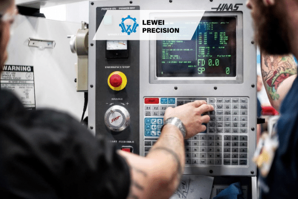
Step 3: CNC Machine Setup
Before the CNC machine can begin the cutting process, the workpiece must be set up. This involves securing the material onto the machine bed or fixture, and loading the appropriate tools into the tool holder.
Key Factors in CNC Setup:
- Tooling: The choice of tooling (e.g., end mills, drills, lathes) depends on the part material and geometry. Proper tool selection is critical for achieving the desired surface finish and accuracy.
- Workholding: The workpiece must be securely clamped or fixtured to ensure it remains stationary during the cutting process. This is particularly important for high-precision parts where any movement could lead to dimensional inaccuracies.
- Machine Calibration: The machine must be calibrated to ensure the correct positioning of the tool and the workpiece. Errors in calibration can result in misalignment and flawed parts.
Real-World Example:
In the automotive industry, CNC machine setup might involve setting up a 5-axis milling machine to create a part with intricate features such as complex contours and holes. The workpiece, made from a high-strength aluminum alloy, is clamped using a custom fixture, ensuring it doesn’t shift during machining. The right cutting tools are selected to handle the material‘s hardness and achieve the required surface finish.
Step 4: Machining the Part
With the machine set up, the CNC process begins. The machine reads the G-code generated by the CAM software and follows the instructions to cut the material to the desired shape.
Key Elements of the Machining Process:
- Tool Movements: CNC machines can operate along multiple axes (typically X, Y, and Z), allowing for complex, multi-dimensional cuts. More advanced machines may also include rotational axes (A, B, C) to further improve flexibility.
- Cutting Parameters: Cutting speed, feed rate, and depth of cut are all parameters that influence the machining process. These factors are determined based on material properties and part requirements.
- Coolant Use: In many CNC processes, coolant is used to reduce heat buildup, prevent tool wear, and improve surface finish. The type and amount of coolant used depend on the material being machined.
What Can Go Wrong During Machining?
While CNC machining offers high precision, various issues can arise:
- Tool Wear and Failure: Over time, tools may wear down or break, leading to poor surface finishes or dimensional errors.
- Material Distortion: The machining process can induce stresses in the material, leading to warping or distortion, especially for thin-walled or large parts.
- Machining Errors: Issues such as incorrect tool paths or machine malfunctions can result in parts that are out of tolerance.
Engineers must monitor these potential issues and take corrective actions as necessary to ensure the final product meets specifications.
Step 5: Post-Machining Operations and Quality Control
After machining, parts typically undergo additional processes to improve quality and functionality.
Common Post-Machining Operations:
- Heat Treatment: Some parts require heat treatment to improve hardness, strength, or other mechanical properties.
- Surface Finishing: Processes such as polishing, anodizing, or coating may be used to improve the part’s appearance, corrosion resistance, or surface finish.
- Inspection and Testing: Final inspection ensures that the part meets the required specifications. This can include dimensional checks, surface roughness measurements, and functional testing.
Real-World Scenario:
In the aerospace industry, after a part is machined, it may undergo a heat treatment process to improve its strength before being subjected to rigorous quality control tests. These tests could include X-ray inspection to detect internal flaws or non-destructive testing (NDT) to ensure the part is free of cracks.
Step 6: Packaging and Delivery
Once the part has passed inspection, it is packaged for delivery. Packaging must protect the part from damage during shipping and may also involve marking the part with relevant documentation, such as certificates of compliance or inspection reports.
Trade-Off Considerations in Packaging:
- Cost vs. Protection: High-value or delicate parts may require more robust packaging, which can increase costs. For less critical parts, simpler packaging solutions may be sufficient.
- Lead Time: Packaging processes must be efficient to meet delivery deadlines, especially in time-sensitive industries like medical devices or automotive manufacturing.
CNC Machining FAQs
1. What materials can be machined using CNC machines?
CNC machining can handle a wide variety of materials, including metals (e.g., aluminum, steel, titanium), plastics (e.g., ABS, POM), and composites (e.g., carbon fiber). The material selection depends on factors such as the part’s intended use, required strength, and machinability.
2. How do engineers ensure part accuracy in CNC machining?
Engineers ensure part accuracy by carefully selecting tools, monitoring machining parameters, and using advanced machine calibration techniques. They also conduct regular inspections and quality control checks throughout the machining process.
3. How does the CNC machine determine cutting speeds?
Cutting speeds are determined based on the material being machined, the type of tool being used, and the desired surface finish. CAM software typically suggests optimal cutting speeds, but adjustments may be made based on experience or material behavior.
4. What is the role of coolant in CNC machining?
Coolant helps reduce the heat generated during machining, preventing tool wear, improving surface finish, and preventing thermal damage to the material. It also assists in removing chips and debris from the cutting area.
5. Why do engineers prefer CNC machining over manual methods?
CNC machining offers higher precision, repeatability, and efficiency compared to manual machining. The ability to program complex tool paths and make rapid adjustments also leads to greater flexibility in manufacturing.