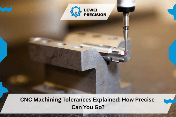
Getting CNC machining tolerances right can make or break your manufacturing project. Machine shops today work with incredible precision – some CNC machines hold tolerances down to ±0.0025mm. That’s about a quarter of a human hair’s width. Pretty impressive when you think about it.
Standardized Tolerances for CNC Machining
Most shops follow ISO 2768 for general tolerance work. This standard breaks things down into four main groups: Fine (f), Medium (m), Coarse (c), and Very Coarse (v). Here’s what each one covers:
- Fine (f): When you need things super precise with barely any wiggle room
- Medium (m): Good middle ground between being accurate and actually makeable
- Coarse (c): Works fine for parts where exact dimensions aren’t critical
- Very Coarse (v): Loosest tolerance class for basic applications
If you don’t call out specific tolerances on your prints, most shops default to around ±0.1mm. But depending on what you’re making and what material you’re using, they can go much tighter.
| Nominal Size Range | Fine (f) | Medium (m) | Coarse (c) | Very Coarse (v) |
| 0.5-3mm | ±0.05mm | ±0.1mm | ±0.2mm | ±0.5mm |
| 3-6mm | ±0.05mm | ±0.1mm | ±0.3mm | ±0.8mm |
| 6-30mm | ±0.1mm | ±0.2mm | ±0.5mm | ±1.2mm |
| 30-120mm | ±0.15mm | ±0.3mm | ±0.8mm | ±2.0mm |
Tolerancing Guidelines for CNC Machining
Bilateral tolerances work both ways – your part can end up bigger or smaller than the target. So ±0.06mm means you could get a part that’s 0.06mm under or over what you asked for.
Unilateral tolerances only go one direction. Sometimes you need a hole that can’t be smaller than a certain size, or a shaft that can’t be bigger. That’s where unilateral comes in handy.
Limit tolerances just give you a range straight up. Like saying “anywhere between 15mm and 15.5mm is good.” Simple and clear.
Surface Roughness Considerations for Machining Tolerances
Surface finish matters more than people realize. Standard CNC work usually gets you about 63 microinches Ra on flat stuff and 125 microinches Ra on curved surfaces.
Want something smoother? You’ll need extra steps:
- Grinding gets you that mirror finish
- Polishing works great for parts people will see
- Special tooling for surfaces that slide against each other
Geometric Dimensioning and Tolerancing
GD&T takes things way beyond basic plus-minus tolerances. Instead of just saying “this dimension needs to be X ± Y,” it controls how flat something is, where holes are positioned, and how round things actually are.
The big ones you’ll see:
True Position: Controls exactly where holes and features end up relative to your reference points. Uses MMC (Maximum Material Condition) or LMC (Least Material Condition) to define when the tolerance applies.
Flatness: Keeps surfaces from warping. Really important on thin parts that like to bow after machining.
Cylindricity: Makes sure holes are actually round and straight, not egg-shaped or tapered.
Concentricity: When you need one round feature perfectly centered with another one.
Perpendicularity: Controls how square surfaces are to each other. Critical for parts that need to assemble properly.
Why High-precision/High-quantity Machining?
Chasing those super tight tolerances like ±0.001″ gets expensive fast. Tools wear out quicker, cycles take longer, and you need more inspection. During big production runs, this really adds up.
High-precision work is different from regular machining:
- Takes longer to set up and program
- Needs specialized cutting tools
- Requires more inspection and measurement
- Environment needs to be temperature controlled
Sometimes you need special processes:
- Wire EDM for complex shapes standard machining can’t handle
- Grinding for surfaces that need to be really smooth
- CMM inspection to verify everything is within spec
Quality Control and Documentation Options
Modern shops have some pretty sophisticated ways to check parts:
Measurement Tools: CMM machines can check multiple dimensions at once and catch problems regular measuring tools might miss.
Paperwork:
- PPAP documentation for automotive and aerospace customers
- Certificates of Conformance proving parts meet spec
- First Article Inspections for new jobs
- Material certs showing what alloy you actually got
The ISO folks are updating their standards too. ISO/DIS 2768 is coming soon to replace the old ISO 2768-1:1989 standard.
| Tolerance Type | Standard Application | Precision Range |
| Standard CNC | General manufacturing | ±0.1mm |
| Precision CNC | Critical components | ±0.02mm |
| Ultra-precision | Aerospace/Medical | ±0.005mm |
Conclusion
Look, tolerances matter more than most people think. They’re not just random numbers someone puts on blueprints. Get them wrong and your parts won’t fit together, or worse, they’ll work fine until they fail in the field. ISO 2768 works great for most situations, but sometimes you need to dig deeper.
Here’s what I’ve learned after years in this business: tighter isn’t always better. Sure, you can hold incredibly tight tolerances if you really need to, but ask yourself if you actually do. Every extra decimal place costs real money.
Find yourself a machine shop that actually understands what they’re doing. Someone who’ll tell you when you’re being too picky and when you’re not being picky enough. Trust me, it makes all the difference.
What tolerance should I expect from standard CNC work?
Most decent shops can hit ±0.1mm without breaking a sweat. If you need tighter than ±0.02mm, expect to pay more and wait longer.
What’s the tightest tolerance possible with CNC?
I’ve seen shops hold ±0.0025mm on the right parts with the right equipment. Going beyond ±0.0001″ gets into specialty territory where costs go through the roof.
Why do people keep mentioning ISO 2768?
Because it saves everyone time. Instead of putting tolerances on every single dimension, you just reference the standard and move on with your life.
Will tight tolerances cost me more money?
Every time. Tight tolerances mean slow feeds, frequent tool changes, constant inspection, and higher scrap rates. Only go tight where it actually matters.
Should I use GD&T on my drawings?
Only if standard tolerances won’t cut it. If you need to control form, position, or orientation between features, then yeah, GD&T is your friend. Otherwise, keep it simple.
References
- International Organization for Standardization. (2025). ISO/DIS 2768 – Geometrical product specifications (GPS) — Dimensional tolerancing. Retrieved from https://www.iso.org/standard/85741.html
- International Organization for Standardization. (2022). ISO 2768-1:1989 – General tolerances — Part 1: Tolerances for linear and angular dimensions. Retrieved from https://www.iso.org/standard/7748.html
- American Society of Mechanical Engineers. (2024). ASME Y14.5 – Dimensioning and Tolerancing Engineering Drawing and Related Documentation Practices.
- Engineers Edge. (2025). General ISO Geometrical Tolerances Per. ISO 2768. Retrieved from https://www.engineersedge.com/mechanical,045tolerances/general_iso_tolerance_.htm
- DIN Standards. (2025). General Tolerances to DIN ISO 2768. Retrieved from https://dau-components.co.uk/wp-content/uploads/2025/02/General_Tolerances_-DIN_-ISO_-2768.pdf